Powertrain
About
- NWH Vehicle Physics 2 uses a physically accurate solver based on torque and angular velocity.
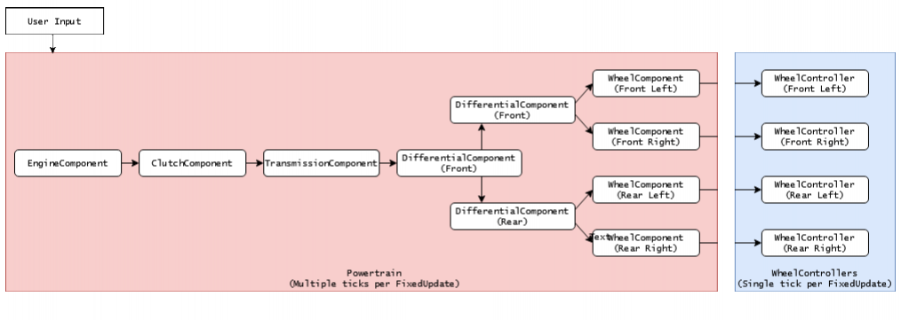
Powertrainin NWH Vehicle Physics 2 is a collection of Powertrain Components such asEngineComponent,ClutchComponent,DifferentialComponent, etc.
- Each component outputs to one or more
PowertrainComponents, except forWheelComponentwhich always outputs toWheelController. EngineComponentwhich acts as a power source andWheel Componentacts as a power sink. The components in-between determine how the power/torque will be transmitted.
Powertrain Component
The PowertrainComponent serves as a foundational class for all powertrain components, including EngineComponent, ClutchComponent, TransmissionComponent, and others.
Each PowertrainComponent possesses the following shared attributes in the Inspector:
Name- The label assigned to the component. Note that altering theNameof a component will reset the * *Outputfor any components that utilize that component.Inertia- Represents the inertia of the component. The inertia of each component contributes to the overall system inertia, which determines the difficulty of spinning the component up or down.Output- Specifies thePowertrain Componentto which torque is forwarded. For certain components, such as *Differential Component, multiple outputs may be present (e.g., left and right wheel).
Keep in mind the following:
- Modifying the
namefield of a component resets all theOutputs for otherPowertrainComponents that rely on that component as an output. - Increasing the
Inertiavalue will cause the component to spin up more slowly when the same amount of torque is applied. - The
Inertiaof aWheelComponentis determined by theWheelControllers mass and radius settings.
Always ensure that the Inertia value is greater than 0!
Engine Component
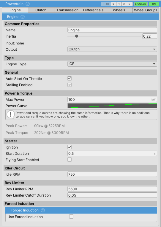
The engine acts as a source of power/torque and updates the components attached to it recursively with the generated torque.
When using the Electric engine, consider setting the output to the Transmission, bypassing the Clutch, as it is not needed.
Inertia
Higher engine inertia results in an engine that is harder to stall. The such engine will also take longer to spin up. Typical values:
- Sports car: 0.2
- Average car: 0.3-0.5
- Semi truck: 1-1.5
Power Curve
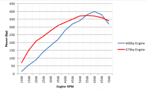
The power curve represents engine power across its RPM range.
X and Y values are normalized where X (0 to 1) represents RPM as a percentage of Rev Limiter RPM and Y (0 to 1) represents power as a percentage of Max Power.
Note that power and torque curves show the exact same data since the power is a function of torque and RPM, so knowing two of the three is enough. Since power curves are usually easier to find, NVP2 uses a power curve instead of a torque curve.
Idler Circuit
The Idler circuit tries to keep RPM at Idle RPM when there is no user input. This is done through throttle modulation so it is still possible to stall the engine if stallingEnabled = true.
Starter
Starter spins up the engine to try and reach the RPM at which the power generated by the engine is enough for it to spin by itself and overcome the losses. The amount of torque needed is automatically calculated based on the engine inertia, Power Curve, and the Start Duration value.
When Flying Start is enabled, the engine spins up instantly without running the starter. This is to give an illusion of the engine already having been started when the vehicle is woken up.
Rev Limiter
Cuts throttle to the engine when RPM reaches Rev Limiter RPM for a duration of Rev Limiter Cutoff Duration.
Forced Induction
ForcedInductionis a part ofEngineComponent. It can be used for both turbocharging and supercharging the vehicle.Power Gain Multiplieradds power on top of the existingMax Powerso the vehicle with 100kW andPower Gain Multiplierof 1.5 will actually produce 150kW.- Boost value affects sound components
TurboWhistleComponentandTurboFlutterComponent. If forced induction is to be used just for the sound effectsPower Gain Multipliershould be set to 1.
Power Modifiers
Power modifiers can be used through scripting to modify the power of the engine. These are functions that return a float which denotes an engine power coefficient. Example:
public float AddBoost()
{
   if(boostIsActive)
   {
       return 1.5f; // Increases power for 50%.
   }
}
...
myVehicleController.powertrain.engine.powerModifiers.Add(AddBoost);
This is a fictional example. A concrete example can be found inside the TCS module which uses this mechanic to limit power when there is wheel spin.
Clutch Component
ClutchComponent can be bypassed by setting the output of EngineComponent directly to the desired PowertrainComponent but this is not recommended as it will cause stalling in most cases.
Clutch Control
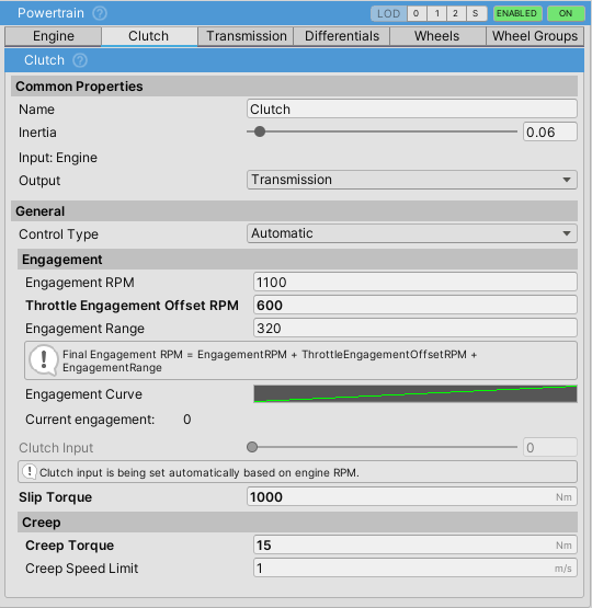
There are two things to note here: clutch engagement and clutch input. Clutch input controls the engagement through the Engagement Curve and is set either automatically, through user input, or scripting/inspector. It is best to think of the Clutch Input value as the pedal position, and the engagement as the “biting point” of the clutch.
Automaticsets the clutch engagement based on the input (engine) RPM.- The final engagement RPM, which is the RPM at which the clutch engagement is at 1 (100%), is the sum of
engagementRPM,throttleEngagementOffsetRPMandengagementRange.
UserInputtype can be used to give control to the user through a gamepad, steering wheel, etc.- When this control type is selected, the clutch is controlled through the
Clutchaxis - check Input section for more info on setting up axes.
Manualtype does not set the clutch value in any way and instead expects to be set externally, either through the inspector or through scripting.
Slip Torque
- When
Has Torque Converteris falseSlip Torqueis used. Otherwise, the clutch will useTorque Converter Slip Torque. \\] - Slip torque for an average clutch should be slightly higher than the maximum engine torque—usually a few hundred to a few thousand Nm.
- Too high
Slip Torquewill result in grabby clutch. - Using too high
Slip Torquevalues can result in torque spikes when the clutch is suddenly released which can impact solver stability in extreme cases.
- Values near zero will result in the engine spinning up as if the clutch is not engaged due to clutch slip.
Creep
- Some automatic transmissions have slight creep when engaged in D or R. This is normally caused by the torque converter (which is essentially a type of clutch) and it allows some of the torque from the engine to escape to the wheels.
Transmission Component
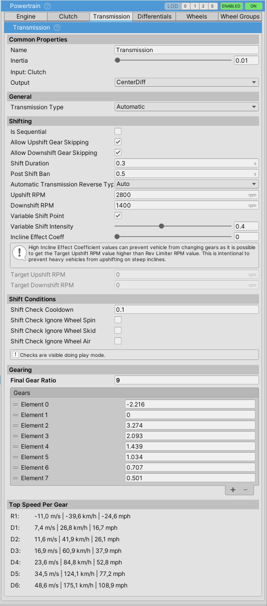
TransmissionComponentis a mandatoryPowertraincomponent. It is always third in thePowertrain.Componentslist.
- NWH Vehicle Physics uses gear ratios – just like the real transmission does.
- If gears are not set up properly the vehicle will not move.
Input Flipping
The asset uses W/S to select the movement direction by default. To use W/S as throttle/brake exclusively go to Control > Input and tick Swap Input In Reverse.
Gearing
- Gearing is assigned through the
gearslist and should be ordered from reverse, then neutral (always 0), then forward gear ratios. - Gear ratios can be adjusted during run-time.
Transmission Types
Manual
- In this type of transmission changing gears can only be done through user input. Check Input Setup for more info on input bindings.
Automatic
- Vehicle shifts gears based on the gear ratios and
Upshift RPM,Downshift RPM,Variable Shift IntensityandIncline Effect Coeffvariables. - Current
Target Upshift RPMandTarget Downshift RPMcan be seen under the under the Shifting section of theTransmissionComponentinspector, during runtime. These values vary depending on the variables mentioned above. IsSequentialmakes the transmission be able to shift only one gear up or down at the time. It has the same effect as ticking bothAllow Upshift Gear SkippingandAllow Downshift Gear Skipping.
CVT
CVT(and eCVT) transmissions have variable gearing ratio dependent on load.- One forward gear in Forward Gears list and one reverse gear in Reverse Gears list should be used. The value of the gear is the maximum gear ratio.
External
Shiftdelegate insideTransmissionComponentis used for changing gears.- This allows for external shifting logic.
- If the delegate is not assigned this option will result in no gear shifts.
Timing
To make shifting more realistic two timers have been added:
Shift Duration- timeTransmissiontakes to change from one gear to another. During this timeEngineComponent's throttle is cut off. Works for all transmission types.Post Shift Bantimer. This field determines minimum time between two shifts. Used to prevent transmission for shifting too often. Only affects automatic transmission types.
Shift Conditions
Transmission will only shift in automatic mode if all the ticked conditions conditions have been met for Shift Check Cooldown seconds:
Wheel Spin- longitudinal slip on all wheels is less thanLongitudinal Slip Threshold(Settings tab)Wheel Skid- lateral slip on all wheels is less thanLateral Slip Threshold(Settings tab)Wheel Air- none of the wheels are in the air.External Shifts Checks Valid- list ofShiftCheckdelegates. All external shift checks must be valid for transmission to be able to shift.
Transmission Gearing Profile
Transmission gearing profiles were deprecated in favor of a simple gears list.
Differential Component
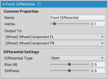
DifferentialComponent is a type of PowertrainComponent that splits input torque between two or more outputs.
There can be multiple DifferentialComponents present on one vehicle and one differential can output to other differentials which is useful for 4WD setup with center differential.
Unused differentials should be removed. E.g. a front differential that none of the other powertrain components (transmission, other differentials, etc.) are outputting to should be removed, as only powertrain components that have a path to Engine are updated.
Differential Types
Open
Torque in open differential is equally split between the left output and right output.
Locked
Locked differential keeps both outputs rotating at same angular velocity.
Limited Slip
Replaces previous separate ViscousLSD and ClutchLSD options. Torque will be sent to the slower spinning wheel, keeping the wheels locked, up to the slip torque value.
External
Can be used to assign an external differential delegate function.
Configurations: 4WD / 2WD / etc.
To achieve a specific drivetrain configuration, different differential layouts can be used. For example:
- RWD: Set the Transmission output to a Differential whose outputs are rear wheels.
- FWD: Same as RWD, but with the Transmission outputting to a Differential whose outputs are front wheels. Remove any unused differentials.
- AWD/4WD: Can be achieved through three differentials; front, rear and center. The center differential should output to front and rear differentials, which then output to front and rear wheels, respectively.
- Adjustable: A configuration of differentials as in the AWD setup can be used, but with the center differential set to Open type. Adjusting the BiasAB slider on the center differential to 0 will make the car FWD and adjusting it to 1 will make it RWD, assuming the first output of the center differential is the front differential.
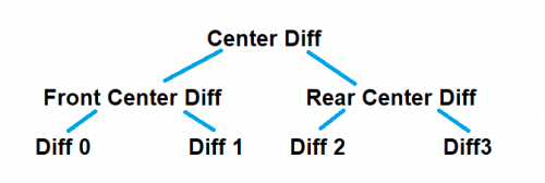
- 8×8 and similar: A trees of differentials can be built, which allows for setups such as 6×6, 8×8, etc. Example:
WheelComponent
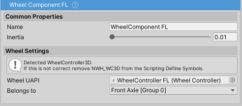
WheelComponentis aPowertrainComponent. It acts as a torque sink and can not output to anotherPowertrainComponentWheelComponentshould not be mixed up withWheelControllerorWheelCollider.WheelComponentinstead interfaces between the powertrain an the wheel.Belongs Tofield determines to which WheelGroup theWheelComponentbelongs to. This determines values such as braking, steering and geometry.Inertiafield gets auto-calculated from assignedWheelController's mass and radius.WheelUAPIfield accepts any wheel controller/collider that uses the WheelUAPI abstract class as its base. The two shipped with the asset areWheelControllerandWheelColliderUAPI. This means that NVP2 can work with any wheel solution as long as it implements WheelUAPI. The reason whyWheelUAPIis not a pure interface is due to the Unity's serialization (or lack of it) for interfaces.
Wheel Group
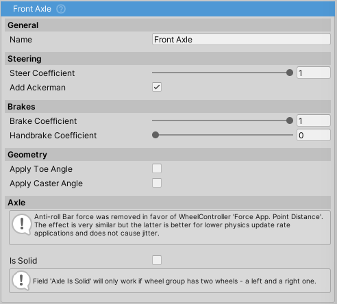
Steering
Steer Coefficientdetermines how much the wheel will steer depending on input. In general cars would haveSteer Coefficientof 1 in front and 0 in the back, except for four wheel steering cars where rear axle usually steers opposite of the front so the value would be negative. Examples:1- 100% steering.0- no steering.-0.5- 50% steering in the opposite direction.
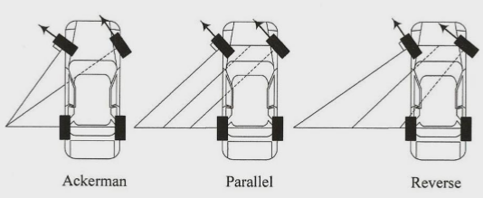
Add Ackerman- check this Wikipedia link for more info about Ackerman Steering setup.- Set automatically for 4-wheel (2×2) vehicles. Not used for motorcycles.
- When setting it manually, set to <0 for Reverse or Anti Ackermann or >0 for Ackermann steering. Field represents percent where 0.12 equals 12% of the steer angle. Following image describes the effect:
Brakes
Brake Coefficient- amount of brake torque used as a percentage ofBrakes⇒Max Torque.Handbrake Coefficient- amount of brake torque applied when handbrake is activated.
Geometry
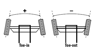
Toe Angle- toe angle in degrees.
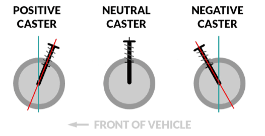
Caster Angle- caster angle in degrees.
- Note: Camber is no longer set through the WheelGroups, except in case of
isSolidbeing true, as in that case the camber is calculated so that the wheels always stay parallel to each other.- For fixed camber the camber is set through the WheelController. For dynamic adjustment of camber, the CamberController component can be attached to the WheelController.
Axle
Axle settings are used only if there are exactly two wheels in the WheelGroup.
Anti Roll Bar Force- deprecated,Force Application Point DistanceonWheelControllershould be used instead. Higher the value, lower the roll.Is Solid- Imitates solid axle and auto-adjusts camber to make sure that both wheels always stay parallel to each other.
